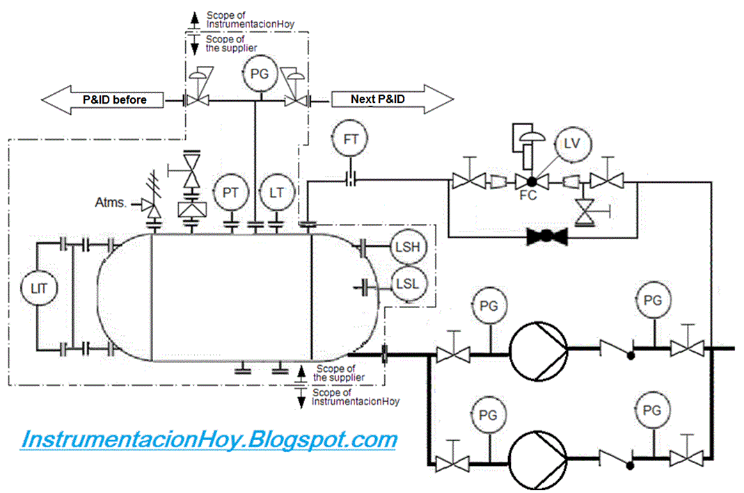

Standardized components, i.e., instrument symbols.Control instrumentation and designation.Usually, P&ID drawings include the following elements: Instead, engineers use the P&ID for this, but they still rely on the PFD to generate the P&ID. But the PFD does not display minor elements such as piping designations and details. It, therefore, illustrates how the plant will work upon installation. In chemical and process engineering, engineers rely on the process flow diagram (PFD), which shows the relationship between the primary equipment within a plant, i.e., how the processes and equipment generally follow one another. What is a Piping and Instrumentation Diagram?


In fact, with Scan2CAD, you can do much more. For this reason, automatic conversion is recommended, and this is where Scan2CAD has thrived and continues to thrive. However, these manual processes are bound to take a lot of time, regardless of whether you are dealing with a single P&ID or multiple P&IDs. Alternatively, you would need to scan the documents and then trace new lines over the lines of the scanned image using a vector graphics software program to convert the raster images into vector images. So, what happens when you encounter such a situation yet you do not have access to the original, digital P&ID? Ordinarily, you would have to redo the P&ID/P&IDs and add the extensions. This, therefore, means that any subsequent changes or extension works of the already-installed plant must again be based on the initial Piping and Instrumentation Diagram (P&ID). Thus, P&IDs provide a blueprint against which installers refer when setting up a plant. This is because they describe the entire engineering design process by showing how pipes interconnect with each other, i.e., the sequence of reducers, branches, control interlocks, and valves, as well as with the instrumentation and equipment, such as pumps and motors. Piping and Instrumentation Diagrams (P&IDs) are essential prerequisites during the installation of pipes and equipment in a given plant.


 0 kommentar(er)
